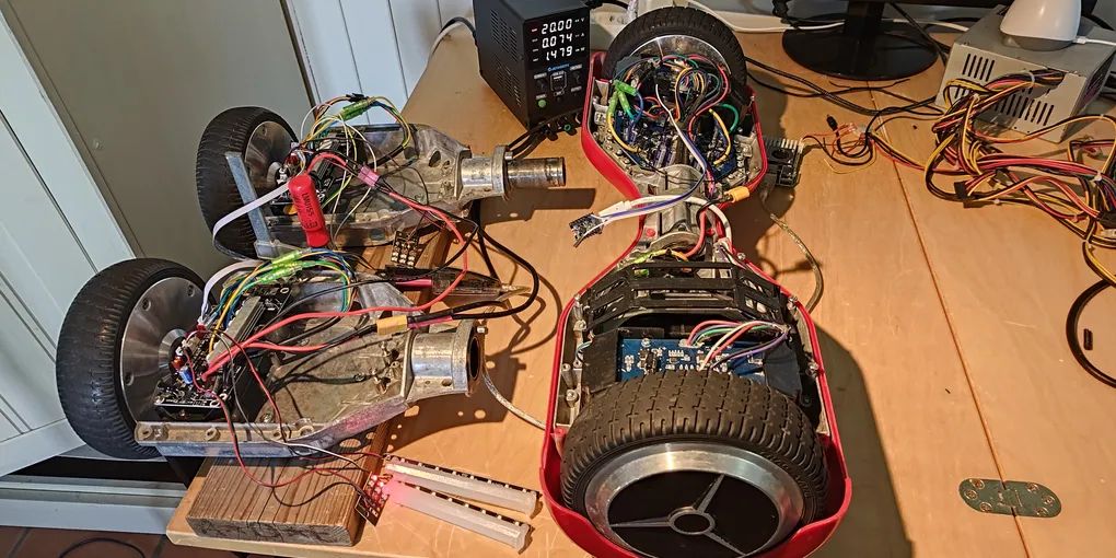
Week 26, 2026: the plan
Two different hoverboards are on the bench this week, and the point of the picture is that they are different. On the left, a split board: each wheel driven by its own little controller, the two halves wired together. On the right, a red chassis half from another board entirely. Different silicon, different pinouts, different idea of how a hoverboard is built. The plan is one firmware that runs on both.
The lineage, and the one thing it shares
Open hoverboard firmware has a well-worn family tree. The original hoverboard-firmware-hack cracked these boards open. EFeru’s FOC firmware became the standard everyone forks, adding field-oriented control and the commutation modes. flo199213’s Gen2 was the first to take on the newer split-board hardware (one controller per wheel instead of one central board) and coined the “Gen2” name for it. RoboDurden’s Gen2.x generalised that across many board layouts with an online per-board config generator. RoboDurden keeps it in two repos: the Gen2.x umbrella (the board-layout defines and the generator) and the buildable GD32 code split out on its own. Between them they cover a lot of boards.
The one thing they all share is that the board is chosen at compile time. EFeru’s firmware is configured by board #defines; RoboDurden’s Gen2.x carries a defines header per board layout and an online generator that hands you a build for your specific board. Change the board, or even change which pin a wire is on, and you compile a different binary. That is the normal way to write firmware, and it works. It is also the thing I want to do differently.
The idea: one binary, two architectures, configured at runtime
The hardware splits into two MCU families, and they are not minor variants of each other, they are two different peripheral architectures:
- The original single mainboards, the kind the original hack and EFeru’s firmware target, where one board drives both wheels. The brain is an STM32F103RCT6 (or a GD32F103RCT6). These are genuine STM32F1: GPIO on the APB bus, the legacy
CRL/CRHconfig registers. - The Gen2 / split boards, the kind RoboDurden’s Gen2.x and flo199213’s Gen2 target, where each wheel has its own half-board talking to its sibling over a serial link. The brain is a GD32F130. The F130 is a Cortex-M3 like the F103, but GigaDevice gave it a newer, ST-style peripheral set: GPIO on the AHB bus with an explicit alternate-function mux, not the F103’s
CRL/CRH. Different registers, different layout.
A normal firmware picks one of these at build time and commits to it. The plan here is a single binary that detects which MCU it is on at boot and drives the right register model either way, sitting on the runtime-hal foundation I have been building. One image covers the F103 mainboards and the F130 split boards. The little sideboards that hang off the original mainboards (the auxiliary boards on the sensor cables, not motor controllers) are F130 parts too, so they come along for the ride.
What the firmware cannot detect is the board layout: which pins drive the motor phases, where the hall sensors and the IMU sit, what the buttons and LEDs are wired to. Every hoverboard firmware needs that description. The difference is where it comes from. Instead of a header compiled into the image, it is configuration stored on the board, written and changed in the field. One binary, reconfigured rather than recompiled.
A note on names, because the community’s are fuzzy: I am calling the classic board a “single mainboard” (the repos’ own word is “mainboard”); you will also hear “12-FET” or “Gen1”, but those are informal, not what the projects call themselves. “Sideboard” and “split board” are different things: a sideboard is the little I/O board on a normal hoverboard, a split board is the per-wheel controller of the Gen2 design. “Gen2” itself is RoboDurden and flo199213’s branding for those split boards.
The configurator
If the board layout lives in configuration, something has to write it. That is a configurator: a browser-based tool, in the spirit of the Betaflight Configurator but online-only, that connects to a board (over USB through a small bridge, or wirelessly over the board’s own Bluetooth), reads its current settings, and writes the layout and tuning back. No toolchain, no rebuild, no reflash to change a setting. Pick your board, describe how it is wired, save it to the board.
The bar for the week
The headline feature is the runtime-config path, so that is what to prove first, end to end on real hardware: set one setting on a real board from the configurator and read it back. Web tool to a board, value written into the on-board store, value read back out. It is a small thing to demo and the whole architecture underneath it, the storage layer, the link, the bridge, has to stand up for it to work. Make that round trip, on a real board, and the runtime-config idea stops being a claim. The motor already spins under six-step commutation on both an F103 and an F130 from one image; this week is about the configuration half of “configured at runtime.”